


 Home
Home

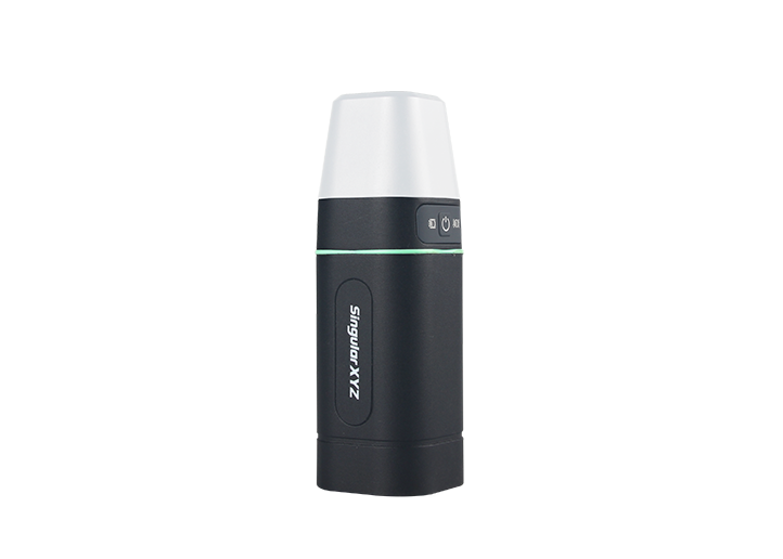
Orion ONE
GNSS Receiver
GNSS Receiver
learn more


 2025-05-20
 Chloe
Chloe


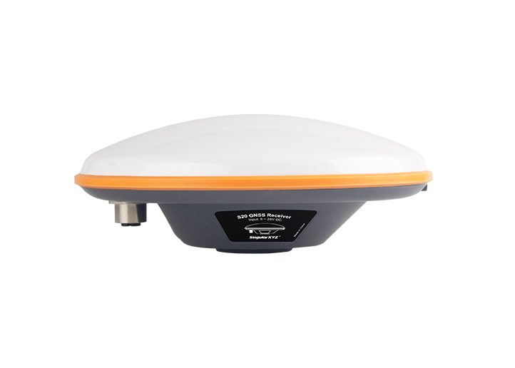
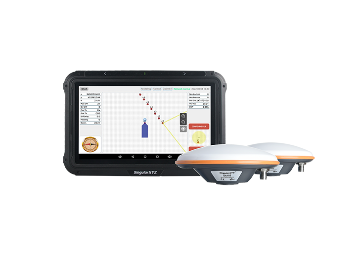
Most surveyors are well-acquainted with the various models and features of GNSS receivers—but have you ever wondered what's hidden inside that compact and rugged housing? Despite differences in shape or manufacturer, most GNSS RTK receivers share a common internal architecture designed to ensure optimal performance in signal tracking, processing, and power management.
In today's blog, let's take a closer look at the internal structure of a GNSS receiver and explore each key component inside.


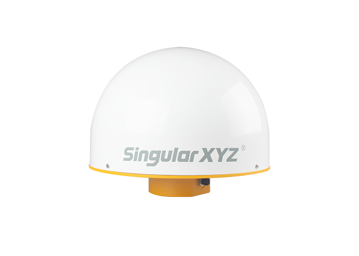
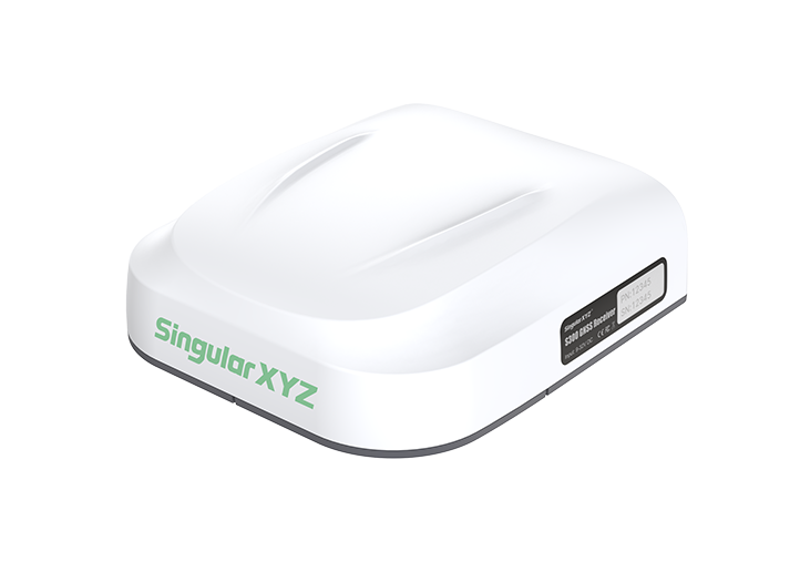
The upper shell forms the outermost protection for the receiver. Typically built from reinforced plastic, it offers durability against physical impact and environmental conditions. It's also often designed with antenna placement and signal transmission in mind, keeping GNSS signal loss to a minimum.
Functions:
Provides structural integrity
Shields internal components from water, dust, and shock
Allows for GNSS signal transparency when using non-metallic materials
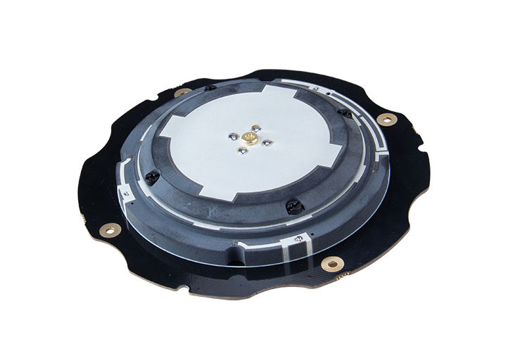
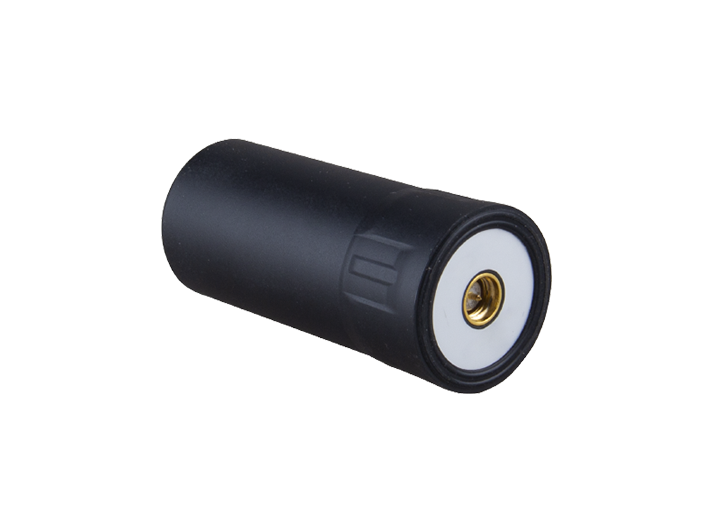
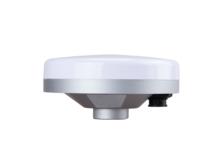
At the heart of every receiver is the GNSS antenna, responsible for capturing signals from multiple satellite constellations. Depending on the receiver's application, it may use a geodetic or helical antenna to optimize signal quality and consistency.
Functions:
Receives GNSS signals (L1/L2/L5, etc.) from satellites
Supports multi-constellation, multi-frequency tracking
Crucial for positioning precision and signal stability
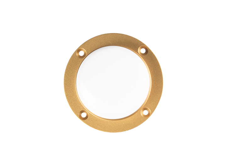
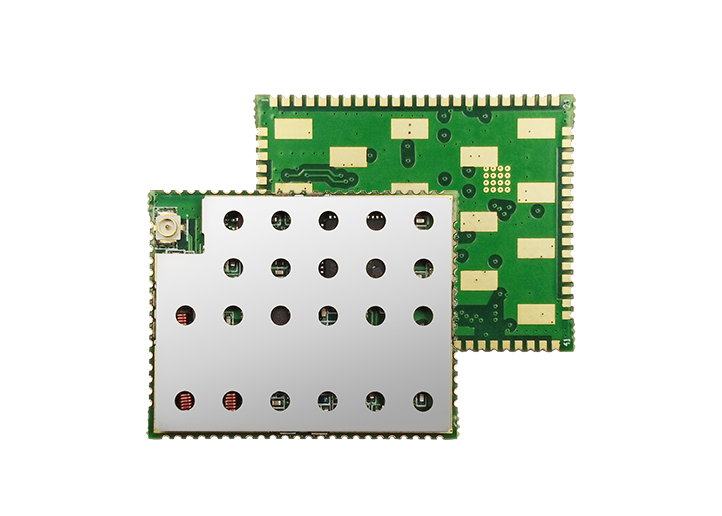
Placed directly under the antenna, the shielding cover is a metal layer that isolates the antenna from potential electromagnetic interference (EMI) caused by internal electronic components.
Functions:
Reduces signal distortion caused by board-level EMI
Helps maintain GNSS signal integrity
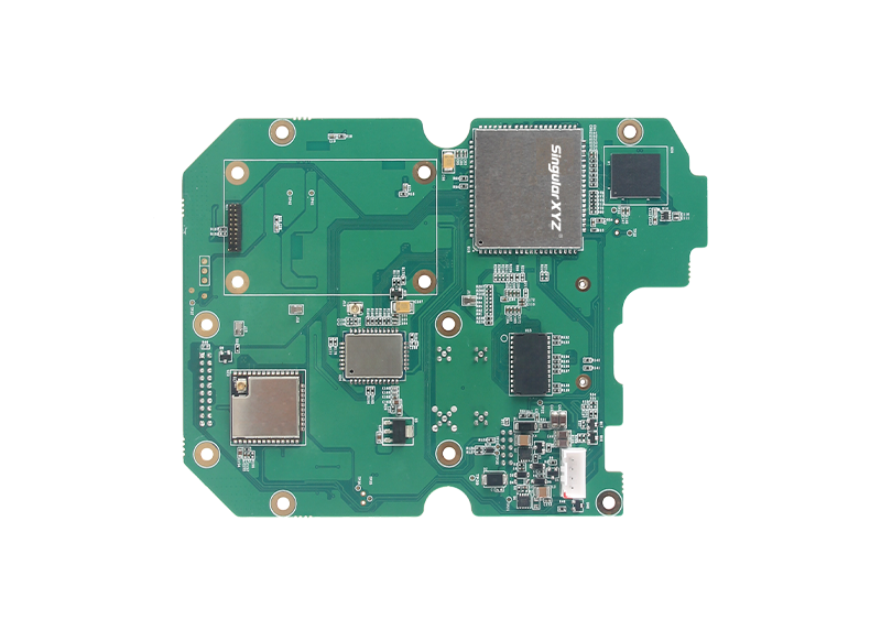
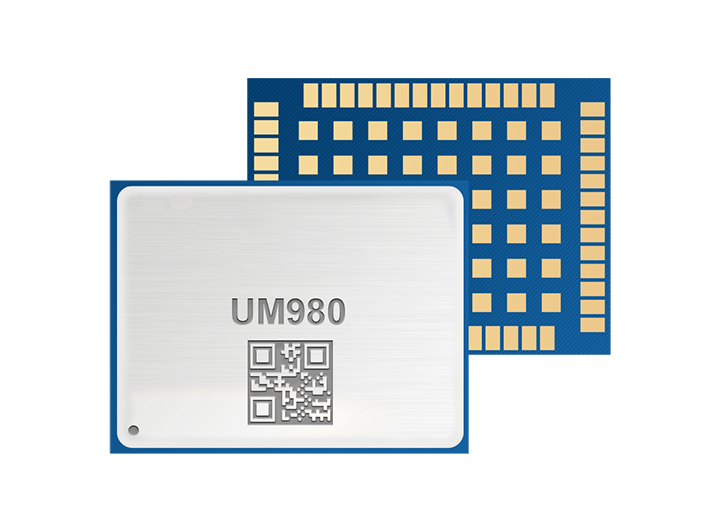
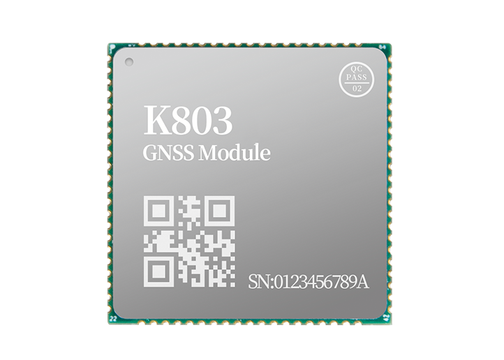
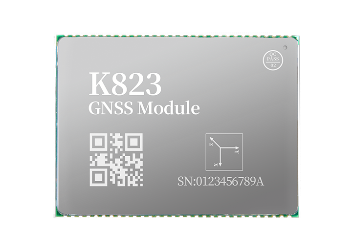
The mainboard is the receiver's brain. It houses the GNSS engine, processing unit, communication modules (radio, Bluetooth, Wi-Fi, 4G), and IMU module. It executes positioning algorithms, processes correction data, and controls all system operations.
Functions:
GNSS signal decoding and real-time processing
Integration with communication and sensor modules
Power and memory management
Most RTK receivers are equipped with internal rechargeable batteries that provide long-lasting field operation. Battery design focuses on capacity, energy efficiency, and safe thermal performance.
Functions:
Provides power to all components
Includes power management circuits for safety and efficiency
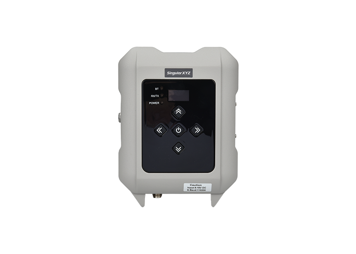
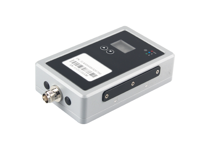
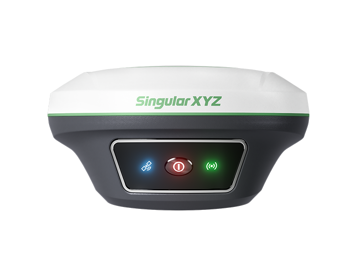
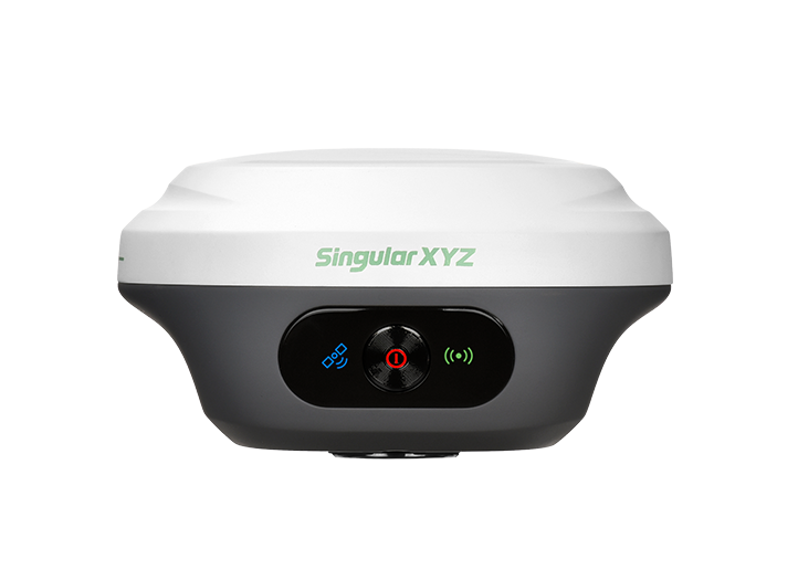
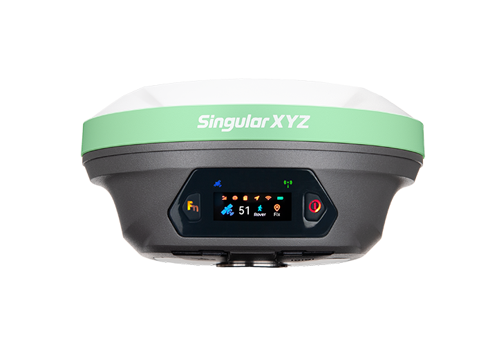
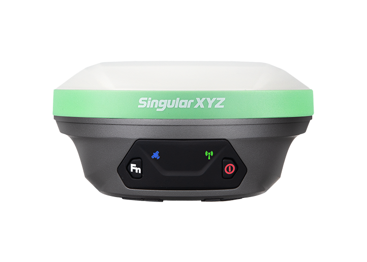
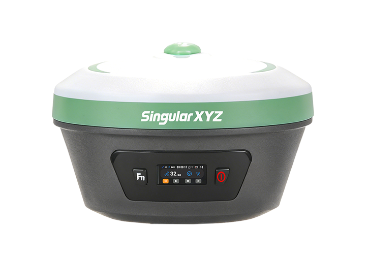
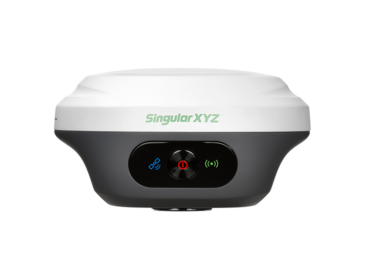
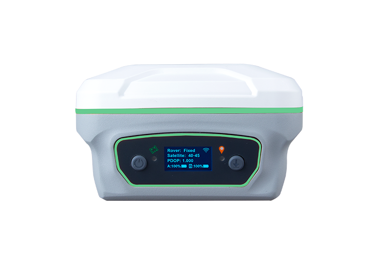
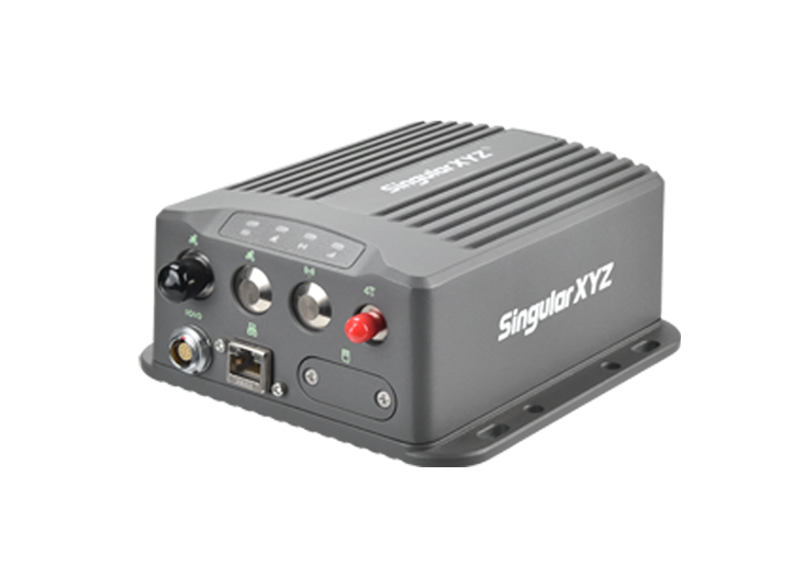
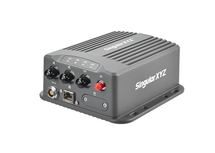
The front panel is the user's direct interface with the receiver, which is normally on the lower shell. It typically includes status LEDs, function buttons, and sometimes a screen for easy configuration and operation.
Functions:
Displays working status (power, satellite, radio, Bluetooth, etc.)
Allows quick start, stop, or mode switching
Improves usability in the field
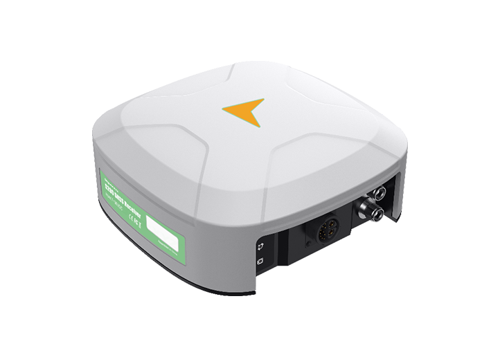
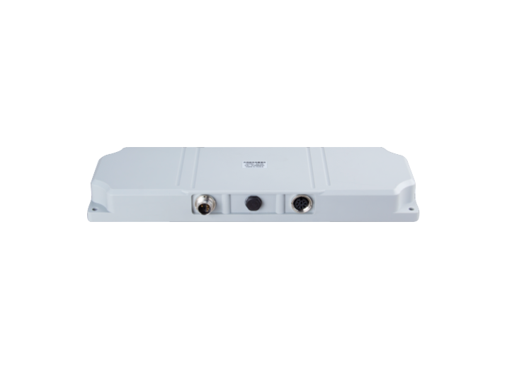
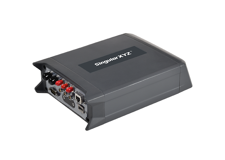
The lower shell completes the enclosure and often integrates both the mounting system and external interface connectors. Like the upper housing, it ensures durability and protection, while in some models it also plays a role in heat dissipation. Commonly made of high-strength materials like magnesium or aluminum alloy, it is designed to endure harsh outdoor conditions.
Functions:
Structural support and protection
Heat conduction and waterproof sealing
Interfaces for tripod or pole mounting
External connectors like SIM card slot, USB port, radio antenna port, and power interface
Although different GNSS receivers may vary in design, features, or branding, their internal architecture remains largely consistent and purpose-driven. From the GNSS antenna at the top to the mainboard and power system inside, each component plays a critical role in delivering stable, centimeter-level positioning in real-world field conditions.
Understanding these components not only helps you choose the right receiver for your work but also gives insight into how positioning technology achieves such impressive accuracy in challenging environments.