In our previous post, we explained the basics of GNSS antenna calibration and the role of NGS certification. This time, we'll take a closer look at the calibration files produced by NGS—ANTEX and ANTINFO—and how these files can be understood and applied in real GNSS workflows.
1. What Are ANTEX and ANTINFO Files?
NGS publishes antenna calibration results in two standardized formats:
ANTINFO (.txt) – a concise summary file, showing average Phase Center Offsets (PCO) and simplified Phase Center Variations (PCV).
ANTEX (.atx) – a comprehensive file, widely used in GNSS software, containing detailed frequency-dependent and direction-specific PCO/PCV models.
Both formats describe how the antenna's phase center behaves, but at different levels of detail.
2. Inside an ANTINFO File
The ANTINFO file is designed to be human-readable. It typically includes:
Antenna Model Information (e.g., manufacturer, part number)
Average Offsets (PCO values) along the North, East, and Up axes
PCV Corrections summarized over elevation/azimuth angles
Example (excerpt): visit https://www.ngs.noaa.gov/ANTCAL/LoadFile?file=SITX1_NONE.003

How To Read It:
(1) Line 1 – Identification
SITX1: Antenna model code.
NONE: Serial number field. When "NONE" is shown, the calibration applies to the antenna type (generic model) rather than a specific individual unit.
Singular XYZ X1 GNSS Receiver: Receiver type
PN: 12211: manufacturer PN.
NGS: Organization performing the calibration.
( 5 ): Internal dataset/method identifier used by NGS to track the calibration session.
24/08/01: Calibration date (YY/MM/DD).
(2) Line 2 – Phase Center Offset (PCO)
Values are given in millimeters in the North, East, Up (NEU) local antenna frame:
North = +2.3 mm
East = +0.3 mm
Up = +63.5 mm
This defines the vector from the antenna reference point (ARP, usually the mounting surface) to the average electrical phase center (APC).
Subsequent Lines – Phase Center Variation (PCV)
These numbers model how the APC shifts with satellite signal direction:
A total of 19 values are listed, corresponding to zenith angles from 0° to 90° in 5° steps.
Zenith angle z is related to satellite elevation el by z = 90° – el.
Example: At satellite elevation 30°, z = 60°, which corresponds to the 13th value in the list (+1.6 mm).
In summary, ANTINFO is compact, making it good for quick reference or documentation, but not detailed enough for full GNSS processing.
3. Inside an ANTEX File
ANTEX (Antenna Exchange Format) files are machine-readable and structured. They contain:
Header Information: file version, reference antenna, calibration method
Antenna Definition: type, serial number, calibration institution (NGS)
Frequency Blocks: detailed PCO and PCV values for each GNSS signal (L1, L2, etc.)
Elevation/Azimuth Grid: PCV corrections across a full range of angles
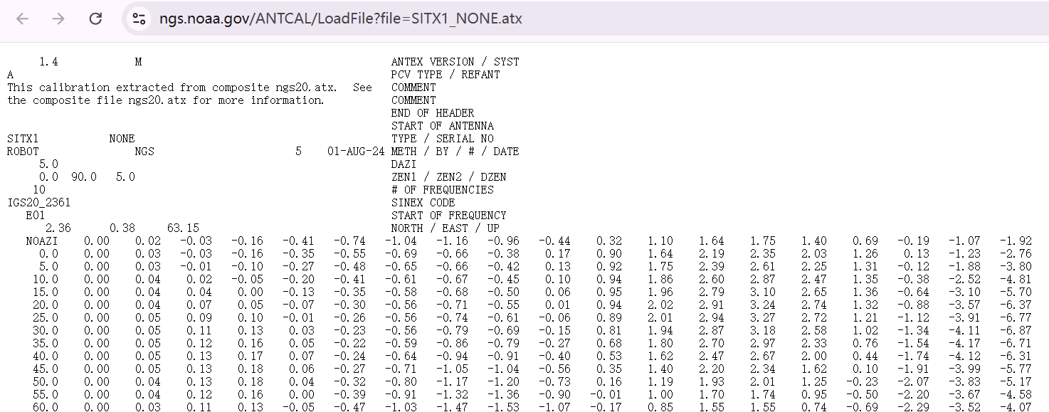
Example (excerpt): visit https://www.ngs.noaa.gov/ANTCAL/LoadFile?file=SITX1_NONE.atx
How To Read It:
(1) Key Fields
ANTEX VERSION / SYST: File format version (1.4), system (M = multi-GNSS).
PCV TYPE / REFANT: Calibration type; here A = absolute.
TYPE / SERIAL NO: SITX1 is the model, NONE again means type-level calibration.
METH / BY / # / DATE: ROBOT / NGS / 5 / 01-AUG-24 → robotic calibration, performed by NGS, internal ID (5), date.
DAZI: Azimuth step (here 5°) for azimuth-dependent PCV tables.
ZEN1 / ZEN2 / DZEN: Zenith angle range (0–90°) and increment (5°).
# OF FREQUENCIES: Number of GNSS signal frequencies covered (here 10).
START OF FREQUENCY: Each block defines calibration for one signal (e.g., E01 = Galileo E1).
NORTH / EAST / UP: PCO values for that specific signal frequency.
(2) PCV Blocks
NOAZI block: One-dimensional PCV vs. zenith angle (like ANTINFO).
AZI blocks: Two-dimensional PCV grids, giving residuals as a function of both azimuth and zenith.
When a GNSS software package applies these models, it interpolates between zenith and azimuth grid points to compute the correction for each satellite direction.
(3) Worked Example
If a satellite is at elevation 30° and azimuth 140°:
Zenith angle z = 60°. Interpolate in the PCV table at z=60°.
If azimuth-dependent data exist, interpolate between the closest azimuth slices around 140°.
Add the interpolated PCV to the PCO values (NEU) for that frequency.
These files are essential for high-precision workflows because most GNSS processing engines (e.g., scientific software, post-processing packages) can directly ingest ANTEX to apply corrections.
4. How to Use These Files in Practice
Post-Processing: Import ANTEX calibration files into GNSS software (e.g., SingularXYZ PProcessing, Trimble Business Center, GAMIT/GLOBK, etc.) to correct antenna biases.
CORS or Base Stations: Configure the antenna model with its calibration file so that reference data is traceable and compatible across networks.
Documentation: Attach ANTINFO summaries to survey reports for transparency and traceability.
5. Why It Matters
By applying ANTEX and ANTINFO data, surveyors and GNSS professionals can:
Reduce systematic errors from antenna biases
Improve network consistency (especially across multi-antenna setups)
Ensure alignment with standards for geodetic and infrastructure projects
Antenna calibration is one of the less visible but most influential factors in achieving centimeter-level GNSS precision. By understanding phase center offset (PCO) and phase center variation (PCV), and by using standardized calibration data from trusted sources such as NGS, survey professionals can minimize antenna-related biases and achieve more reliable positioning results.


 Horus Visual & Laser
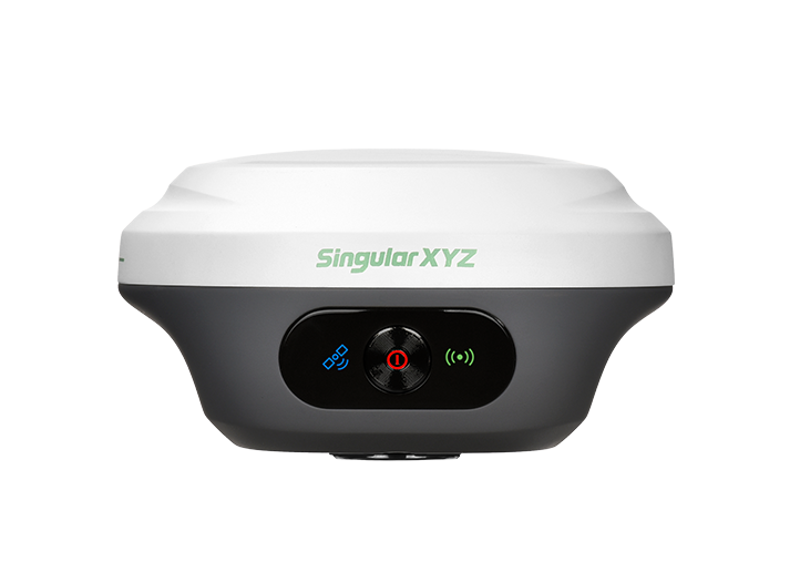 Orion ONE
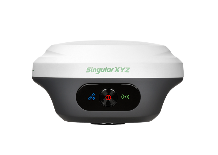 Orion ONE
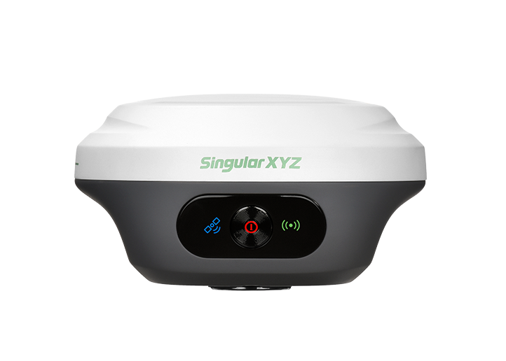 Orion ONE
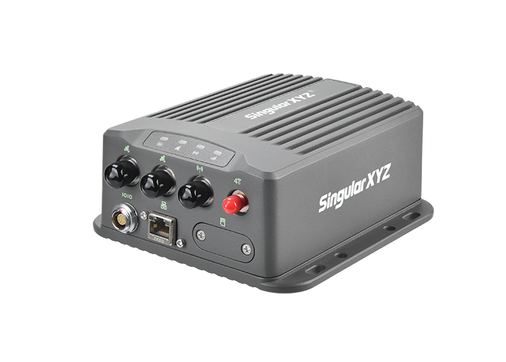
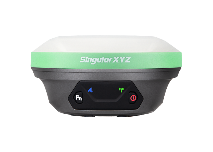 X1 GNSS Receiver
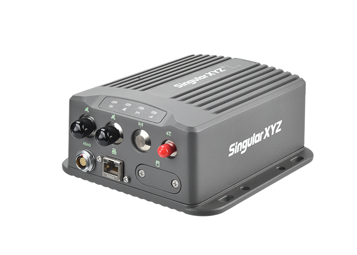
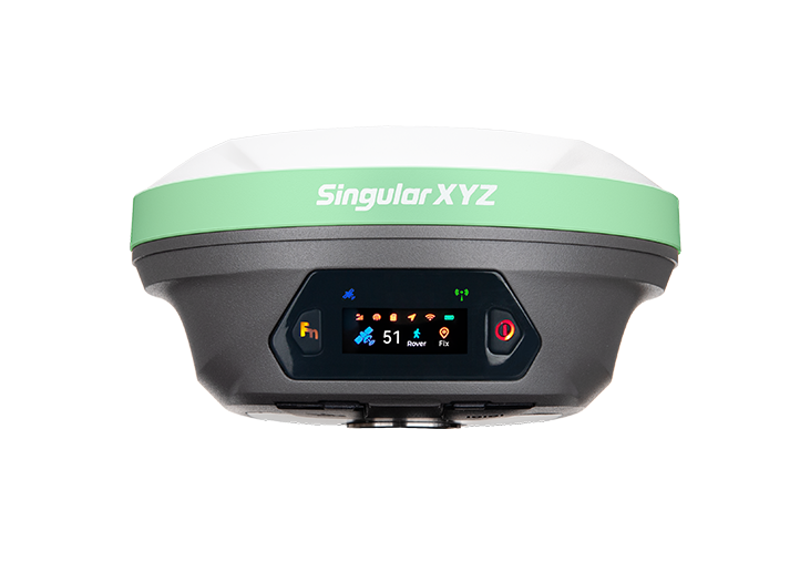 X1 Pro GNSS Receiver
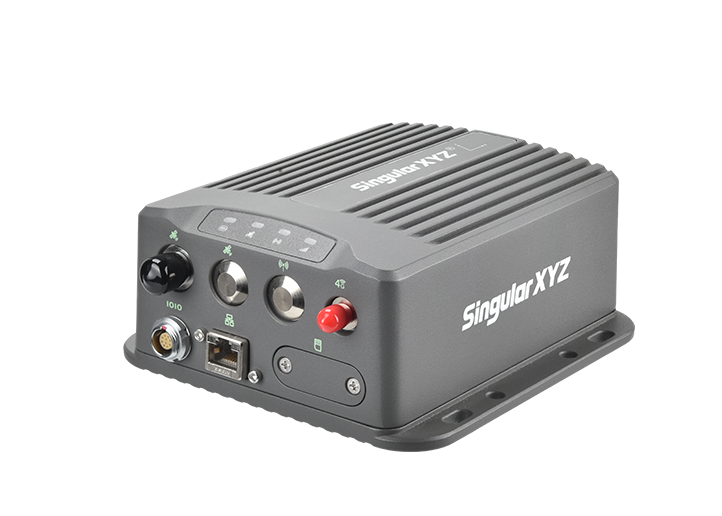
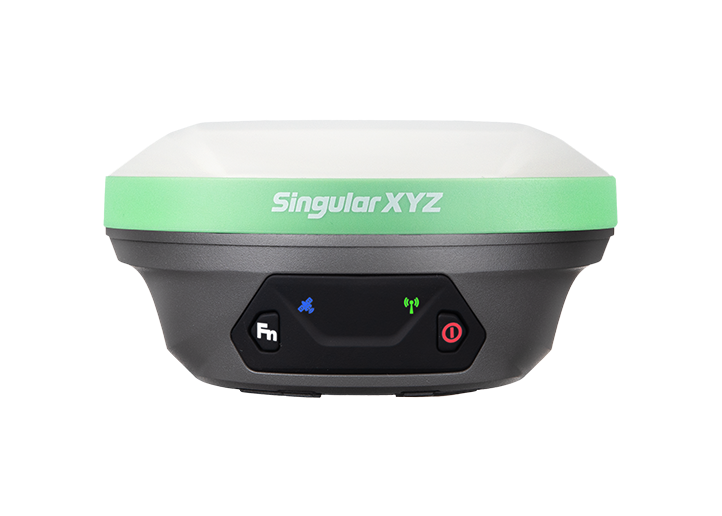 X1 Lite GNSS Receiver
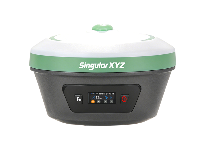 Xbase
Xbase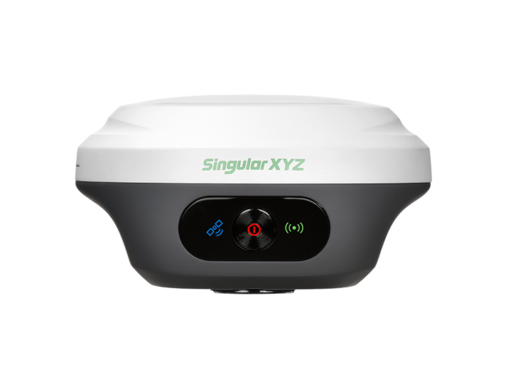 Z1 GNSS Receiver
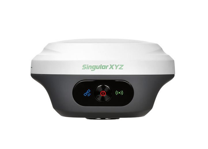 Z1 Lite GNSS Receiver
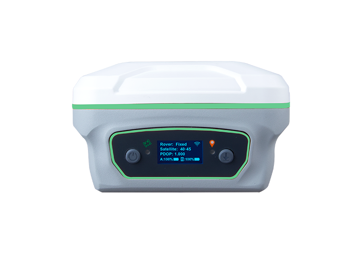 Y1 GNSS Receiver
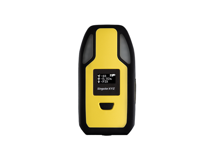 P2 Plus GNSS Receiver
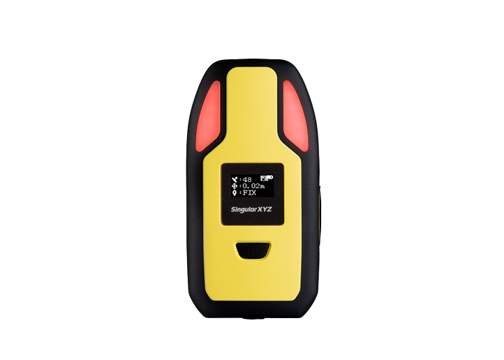 P2 GNSS Receiver
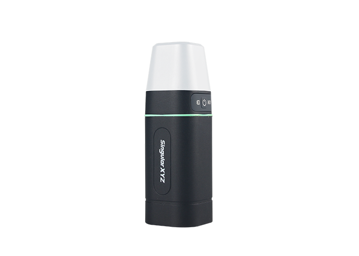 Sfaira ONE Plus GNSS Receiver
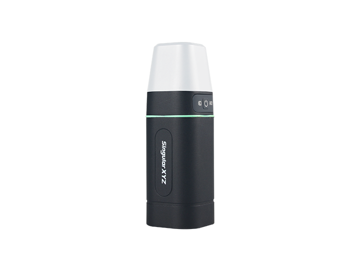 Sfaira ONE GNSS Receiver



















 Home
Home


