


 Home
Home

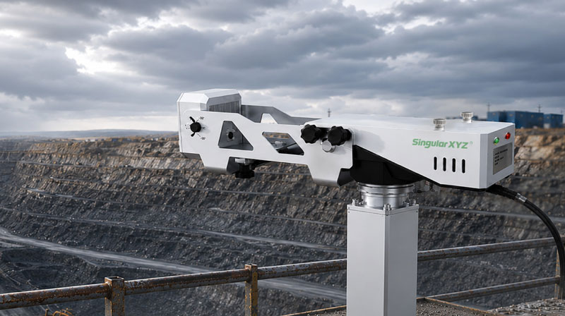
Horus Visual & Laser
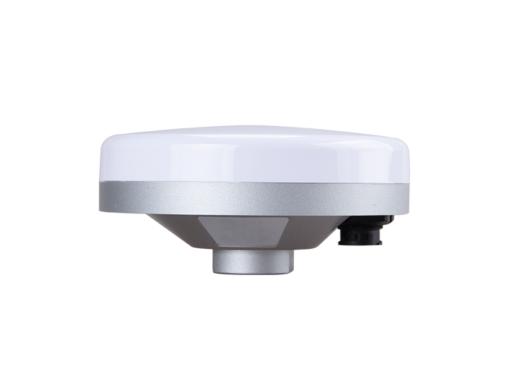
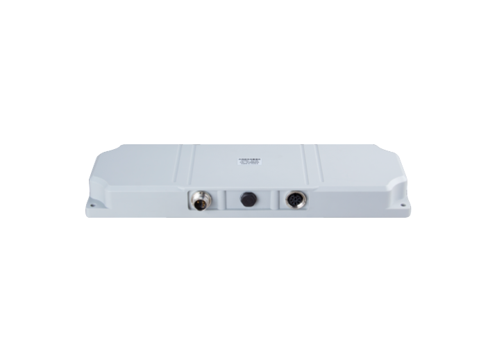
GNSS Receiver
GNSS Receiver
learn more


 2025-11-25
 Chloe
Chloe


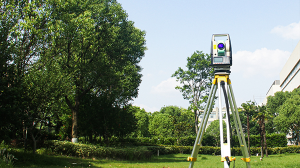
When working with GNSS receivers in real-world surveying, coordinate systems are often the first source of confusion—especially when switching between latitude/longitude and projected systems. To make GNSS coordinates practical for engineering calculations, we often use a map projection to convert the curved surface of the Earth into a flat, grid-based system.
One of the most widely used projections is the Universal Transverse Mercator (UTM) coordinate system, which divides the world into 60 narrow zones to reduce distortion. Understanding which UTM zone your site belongs to—and why it matters—is essential for achieving accurate positioning, correct map alignment, and consistent coordinate outputs across your surveying workflow.
In this blog, we will introduce the concept of projections, how UTM zones work, and how to set up UTM in SingularPad.
A projection is a method for representing the 3D curved surface of the Earth on a 2D plane. Because the Earth is not flat, some distortion of distance, area, or shape is inevitable when projecting coordinates. Different projections are designed to minimize distortion for specific uses.
Latitude/Longitude are angular coordinates that describe positions on the globe but are not convenient for measuring distances or areas in meters.
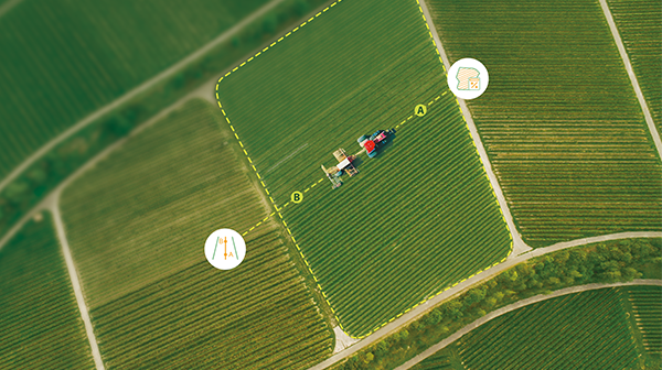
A projected coordinate system like UTM converts geographic coordinates into a flat, meter-based grid that is practical for surveying, mapping, and engineering applications.
The UTM system is a global grid projection based on the Transverse Mercator projection, which aligns a cylindrical projection along a central meridian. Each zone is narrow (6° of longitude) to keep distortion low.
Earth is divided into 60 zones, numbered 1–60 from west to east.
Each zone is split into Northern and Southern Hemispheres.
Positions are expressed in Easting (x) and Northing (y) meters, along with the zone number and hemisphere.
Example:
UTM 32N 432100 5758200

Meter-based coordinates allow precise distance, area, and offset calculations.
Each zone has minimal distortion in its 6° width, suitable for engineering and survey-grade accuracy.
Formula: UTM Zone = floor((Longitude + 180) / 6) + 1
Longitude 10.5°E → Zone 32
Longitude –74° → Zone 18
GNSS receiver display or map interface
Project coordinate system settings
Country survey standards
Previous project files or shapefiles
Tip: Always double-check the hemisphere and zone, especially near boundaries or in multi-zone projects.
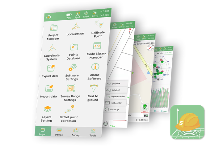
SingularPad makes it easy to work with UTM:
When creating a new project, go to Coordinate System Parameters → Projection Parameter.
Choose the Projection Mode as UTM.
You can input the Central Meridian of your project area or directly click the Survey button to automatically determine the central meridian based on the GPS receiver's current longitude.
The system defaults to the Northern Hemisphere; if your site is in the Southern Hemisphere, tick the Southern Hemisphere option.

Once set, all GNSS measurements and stakeouts will output coordinates in meters, consistent with the chosen UTM zone.
Wrong zone selection → positional shifts of hundreds of meters.
Boundary areas → conflicting datasets, mismatched GIS layers.
Hemisphere mistakes → large Northing differences in Southern Hemisphere.
Multi-zone projects → consider using a local project grid or convert all data to a unified zone.
Best Practices:
Understand the concept of projections before choosing a system.
Verify your UTM zone and hemisphere for every project.
Use software features like SingularPad to automatically determine central meridian and hemisphere.
Coordinate with your team to prevent data mismatches.
UTM is a practical grid system for GNSS surveying because of its meter-based coordinates, low distortion within zones, and clear global standard.
Mastering UTM zones ensures your GNSS receiver, controller, GIS software, and survey drawings remain consistent and reliable throughout your project workflow.