















































































 Home
Home
SV200 INS GNSS Receiver
learn more










 2026-08-10
 Kimberly


In GNSS/INS integrated navigation and vehicle guidance systems, dual-antenna installation orientation directly affects heading accuracy. Since the relative position of the two antennas may vary depending on the vehicle structure and available installation space, the system needs to compensate for the angle difference between the antenna baseline and the vehicle forward direction.
Understanding the relationship between antenna placement, baseline direction, and heading compensation parameters helps ensure correct heading output and reliable navigation performance.
This article explains the definition of dual-antenna heading compensation and introduces four common SV200-INS installation methods with corresponding configuration guidelines.
In a dual-antenna GNSS/INS system, the direction from the primary antenna to the secondary antenna is defined as the baseline direction.
The system calculates the dual-antenna heading angle based on the baseline direction relative to True North. However, depending on the installation position, the baseline direction may not always match the vehicle's forward direction.
For example, the two antennas may be installed:
Along the vehicle's forward direction;
Opposite to the vehicle's forward direction;
Perpendicular to the vehicle's forward direction.
Therefore, a heading installation angle needs to be configured to compensate for the difference between the antenna baseline direction and the actual vehicle direction.
The relationship between these parameters is:
Vehicle Heading = Dual-Antenna Heading + Heading Installation Angle
The heading installation angle is defined within the range of -180° to 180°. If the calculated angle exceeds 180°, 360° should be subtracted to convert it into the corresponding range.
The following figure illustrates the relationship between the baseline direction, vehicle forward direction, and heading compensation angle.
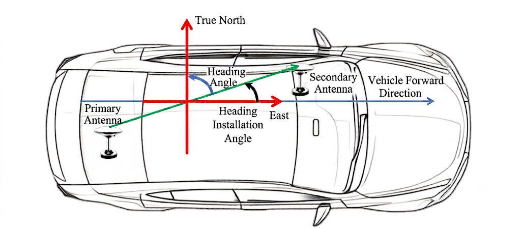
Figure 1. Heading Compensation Diagram
Different vehicle structures may require different antenna installation orientations. The following are four common installation configurations and their corresponding heading compensation settings.
In this configuration, the direction from the primary antenna to the secondary antenna is aligned with the vehicle forward direction.
The heading installation angle is approximately 0°, no additional heading compensation is required.
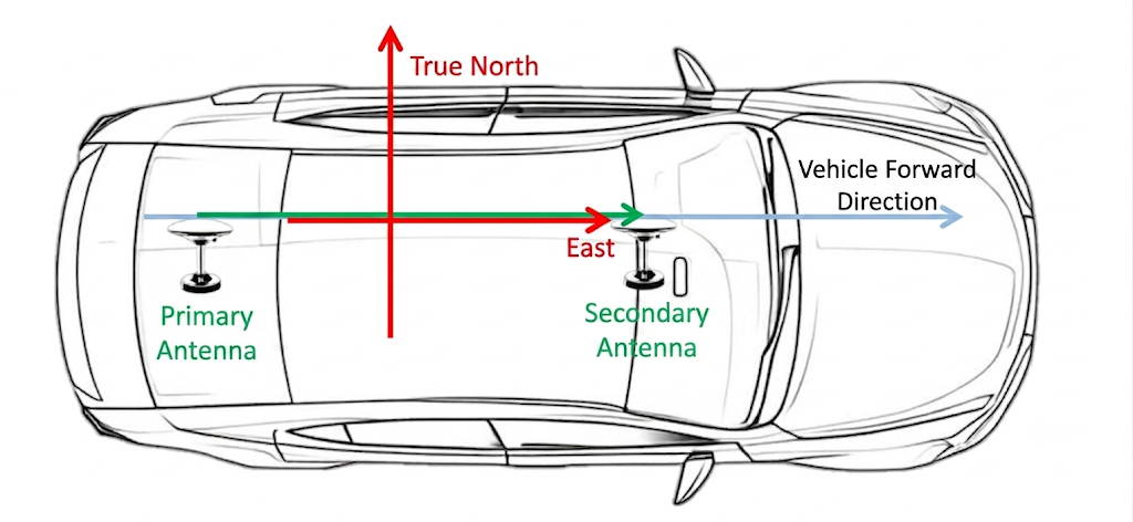
Figure 2. Installation Method 1
In this configuration, the antenna baseline direction is opposite to the vehicle forward direction.
The heading installation angle is approximately 180°. Configure the heading compensation value as 180° to correct the heading output.
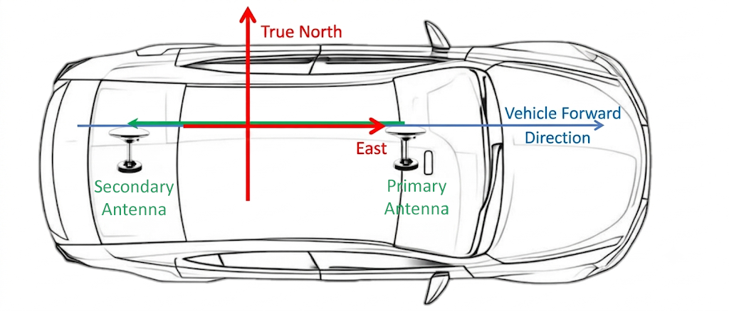
Figure 3. Installation Method 2
In this configuration, the antenna baseline direction is perpendicular to the vehicle forward direction.
The heading installation angle is approximately -90°. Configure the corresponding heading compensation value to match the installation orientation.
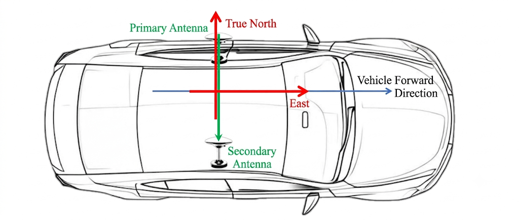
Figure 4. Installation Method 3
In this configuration, the antenna baseline direction is perpendicular to the vehicle forward direction but with the opposite orientation compared with Method 3.
The heading installation angle is approximately 90°. Configure the corresponding heading compensation value according to the actual antenna arrangement.
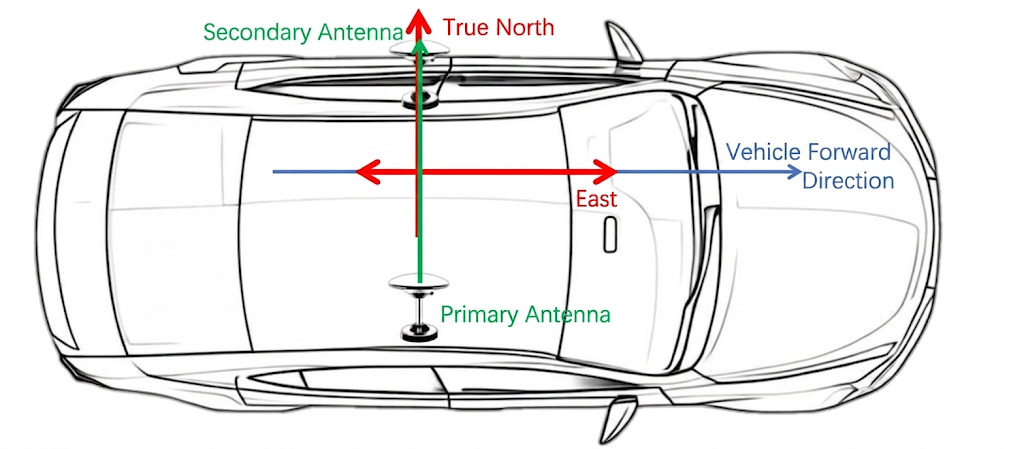
Figure 5. Installation Method 4
Correct dual-antenna installation and heading compensation configuration are essential for achieving accurate heading output in GNSS/INS integrated systems.
Before field operation, identify the relative orientation between the antenna baseline and the vehicle forward direction, then apply the correct heading installation angle. Proper configuration helps ensure reliable navigation performance for vehicle guidance and other high-precision positioning applications.